Gakken's Denshi mini Block Descriptions
Gakken's Denshi mini Block Descriptions
The following is a brief summary of the 50 circuits you can make with the Gakken Otona no Kagaku Denshi mini Block kit (#32). Please note that if you do have this kit and you intend to make these circuits, that I STRONGLY recommend that you double-check all of the blocks before turning on power. At best, having a block in the wrong way will just prevent the circuit from working. I was careless with the jumpers, and I blew out one of the transistors. Gakken was kind enough to send me a replacement for free, with a postage-paid return envelope to send the old block back to them. But, they only have a limited number of replacement blocks, and I doubt they'll mail anything outside of Japan. Further, always make sure the power supply switch is OFF before moving the blocks around (there's no way of knowing if you're going to accidently damage something otherwise).
| 1 | トランジスタ検査機 | Transistor Examination | |||||||
| This is a simple transistor circuit with a floating base pin. By touching the contacts at the base and collector, you can turn on an LED using your body resistance. It's likely that you'll have to moisten your fingers in order to get your body resistance down enough. | |||||||||
| 2 | ダイオード検査機 | Diode Examination | |||||||
| This circuit consists of a plain diode and the red LED. By reversing the direction of the regular diode you can learn about diode polarity. | |||||||||
| 3 | 電気の通り道 | The route of electricity | |||||||
| One of the LEDs (red or green) and 4 wire blocks. Switch in the green LED if you want. It's just a way to test if the LEDs will light up. | |||||||||
| 4 | LEDの点灯電圧 | LED turn on voltage | |||||||
| With this one, you put 2 AA batteries in where the blocks normally go, and use one of the jumpers to make a 1- or 2-cell battery pack. The idea is that the LED will turn on at 3V, but not at 1.5V. | |||||||||
| 5 | LEDの並列。直列回路 | Series/Parallel LED Circuit | |||||||
| As the name states, you use both LEDs in series and parallel as an introduction to series and parallel circuits. | |||||||||
| 6 | 2つのスイッチでLEDをオン/オフ | 2-Switch LED On/Off | |||||||
| While you're using 9 different blocks, only the red LED makes up the actual circuit. The rest of the blocks are just there to hold the jumper wire contacts that act as an open/close switch. This is an introduction to using a switch in a circuit. | |||||||||
| 7 | 導体と不導体 | Conductors and Nonconductors | |||||||
| The circuit consists of the red LED and the 2 jumpers. By touching the jumper pads to a paper clip, an eraser, and your own fingers, you can see how some materials work better as wires, and others as insulation. | |||||||||
| 8 | トランジスタの電流増幅作用 | Current Amplification | |||||||
| This is a reuse of circuit one, but this time with a smaller base resistor. The current through your fingers gets amplified by the transistor to turn on the LED. | |||||||||
| 9 | トランジスタのスイッチ作用 | Transistor Switch | |||||||
| Generally, a transistor is used to amplify a signal in order to increase its strength, as in the transistor radio amplifier circuit. However, it's also the basis of digital circuits, when used as an on-off switch. This circuit illustrates this principle by putting a 1 meg-ohm resistor in series with a 10k-ohm resistor at the transistor input. By shorting out the 10 meg-ohm, you turn the LED at the output on and off. | |||||||||
| 10 | ダイオードの特性 | Special Characteristic of Diodes | |||||||
| Now we get a reworking of circuit 2, but with 2 diodes - one on each side of the LED. This experiment demonstrates that it doesn't matter where along the wire the diode is - if its direction is reversed, current won't flow. | |||||||||
| 11 | 固定バイアス1石+ICアンプ | Fixed Bias Transistor + IC Amp | |||||||
| When we talk about transistors, we generally need to discuss how the transistor is going to turn on. For an amplifier application, we want it turned on 50%, so that as the signal is applied at the base, the collector will swing between Vcc (4.5V) and ground (0V). This "turn on steady state voltage" is called the "DC bias". The idea behind a "fixed bias" is that the normal voltage applied to the base doesn't change. The drawback is that as the transistor heats up, the output voltage will drift. The rest of the circuit is made up of the IC amplifier on the speaker driver circuit board. By putting the mouthpiece cup on the earphone, you have a microphone to drive the input of the transistor amp, giving you a megaphone or a simple eavesdropping device. The microphone is pretty sensitive, so if it's within a foot or two of the speaker, you're going to get severe feedback. | |||||||||
| 12 | 自己バイアス1石+ICアンプ | Self-Biased 1 Transistor + IC Amp | |||||||
| If the drawback to fixed bias is thermal drift, then the alternative is to apply negative feedback from the output of the transistor back into the input. The only difference between circuits 11 and 12 is that the base resistor is connected to the transistor's collector instead of Vcc (the battery). The microphone input is still very sensitive. | |||||||||
| 13 | 2石+ICアンプ (直結式) | 2 Transistor + IC Amp (Common Collector) | |||||||
| Ok, time to explain transistors a little. Transistors have 3 pins - the base, emitter and collector. There are two kinds of transistors, depending on whether the main semiconductor material starts out negative (N) or positive (P) - NPN and PNP. The Denshi mini block kit uses 2 NPN transistors. With NPN, the Emitter goes to ground, the Collector is connected to Vcc (battery voltage) through a "load resistor", and the input signal is applied to the Base pin. It's the Collector pin that changes voltage at the output of the circuit. But, this is just one way of designing an amplifier. A second approach, called "common collector" or "emitter follower", has the Emitter pin doing all of the work. In experiment 13, we have a 2-transistor Common Collector amplifier with a microphone input. Even though circuits 11 through 13 demonstrate different design approaches, they all sound the same. From a results standpoint, they're identical. | |||||||||
| 14 | ダイオド検波ラジオ | Diode Detector Radio | |||||||
| The simplest type of radio is the one that uses a simple crystal and a resistor/capacitor (i.e. - RC) filter. The diode here acts like our crystal. The earphone acts as our earphone. It's a very weak signal, so you may have to connect a longer wire to the antenna to be able to hear anything. | |||||||||
| 15 | ダイオド検波1石ラジオ | 1 Transistor Crystal Radio | |||||||
| Same as #14, but with the 1 transistor amp from #11. Again, having a long antenna may be required to be able to hear anything at all. | |||||||||
| 16 | トランジスタ検波1石ラジオ | Transistor Crystal Radio | |||||||
| Same as #14, but with the self-biased transistor amp from #12. A little bit louder than #15, but not by much. (To be honest, using one of the jumper leads as an antenna, I'm just picking up noise from my laptop.) | |||||||||
| 17 | レフレックス1石ラジオ | 1 Transistor "reflex" radio | |||||||
| Similar to #15, but using 2 diodes for signal feedback. I still can't pull in an AM station (then again, Japan doesn't go in for AM radio much) but I can hear the noise from my laptop CPU much more clearly. | |||||||||
| 18 | ダイオド検波1石+IC アムプラジオ | 1 Transistor Crystal Radio + IC Amp | |||||||
| This is circuit #15, connected up to the IC amplifier circuit board, output to the speaker rather than to the earphone. | |||||||||
| 19 | トランジスタ検波1石ラジオ+IC アムプ | Transistor Crystal Radio + IC Amp | |||||||
| Essentially, this is circuit #18, but without the diode. The signal strength is much greater now, and having the external speaker makes things much easier to work with. It is still fun, though listening to my laptop when it activates the screensaver. | |||||||||
| 20 | 高周波増幅1石+ICアンプラジオ | High Frequency 1 Transistor + IC Amp Radio | |||||||
| This is the first really new circuit approach of the set so far. The transistor is used to amplify the signal from the antenna tuner, and a frequency band pass filter then feeds into the IC amplifier and external speaker. This gives you a better signal out. You're encouraged to substitute the 0.05uF capacitor of the 0.01uF to see what the difference is in frequency response. | |||||||||
| 21 | レフレックス1石+ICアンプラジオ | 1 Transistor "reflex" +IC Amp radio | |||||||
| Basically like #20, but with the dual diode feedback on the transistor. There are now two capacitors you can change values for, one at the input of the transistor, and the other at the output, again changing the frequency response of the circuit. Turns out that there really are 2 AM stations in Kagoshima, and this is the only circuit capable of picking them up. But it is susceptible to screeching feedback attacks. | |||||||||
| 22 | シグナルトレーサー | Signal Tracer | |||||||
| This is the transistor amplifier from circuit 12, but with the earphone instead of the IC amp, and the jumper paddles instead of the antenna tuner. Essentially, the idea is to use this amplifier to listen in to the signals of other circuits to determine if there's a break in a wire or a bad component somewhere. There's no volume control, so you have to be careful about what you try to trace, or you may hurt your ear, or blow out the transistor. May be better to just skip this experiment altogether. | |||||||||
| 23 | 断線警報 (スピーカー式) | Open Switch Alarm (speaker type) | |||||||
| The antenna coil circuit is used to create an oscillator with one transistor, and the resulting tone is fed to the IC amp and external speaker. The jumper wires are used to make a normally-closed switch that shorts out the input of the transistor. When the switch opens, the oscillator activates and the tone is audible. You can change the 0.01uF capacitor to lower the frequency of the oscillator, while tuning it somewhat with the antenna tuning coil. With the 0.01uF cap, the alarm is very attention-grabbing. | |||||||||
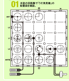
| 24 | うそ発見機(イヤホン) | Lie Detector (Earphone style) | |||||||
| Basically circuit #23, but with the jumper paddles acting as skin contacts instead of the 1 meg-ohm resistor in the oscillator section. A lie detector works on changes in skin conductivity that occur naturally when the body experiences stress (or when you squeeze the contacts harder). The oscillator produces a low-frequency square wave that sounds like clicking in the earphone. When you sweat, the frequency of the clicks increases to make a buzzing sound that is easy to detect. | |||||||||
| 25 | ツインT型発振回路 | Twin-T Oscillator | |||||||
| The name "Twin T" comes from the appearance of the capacitor-resistor structure of the oscillator feeding into the base of the transistor. You can change the frequency of the sine wave produced by changing the 10K-ohm resistors. The book doesn't give the original design frequency, but I expect it's about 1 KHz. | |||||||||
| 26 | 単安定ムルチ回路 | Simple Stable Multi Circuit | |||||||
| According to the description, this is a 1-shot timer, triggered when the input cap of the flip-flop circuit is connected to Vcc (+4.5V). Initially, the red LED starts out turned off. When the contact paddles touch, the LED turns on for about 1 second, then turns off again. | |||||||||
| 27 | 不安定ムルチ回路 | Unstable Multi Circuit | |||||||
| In essence, this is an LED flasher, with the red LED blinking at a 50% duty cycle, about twice a second. (50% duty cycle means that the LED is on for the same length of time as it is off.) | |||||||||
| 28 | 双安定ムルチ回路 | Bi-stable Multi Circuit | |||||||
| Like the previous two circuits, this one is a two-transistor flip-flop (base of one transistor connected to the collector of the other. The difference is that a paddle jumper is connected to a 47uF capacitor attached to the base of one of the transistors. Touching the paddle to Vcc or ground causes the LED at the opposing collector to toggle on and off. | |||||||||
| 29 | 単安定ムルチ回路 (2) | Simple Stable Multi Circuit (2) | |||||||
| Almost the exact same circuit as #26, but with slightly different resistor values to make a 2 second timer. | |||||||||
| 30 | LED 2 個の双安定ムルチ回路 | 2 LED Bi-Stable Multi Circuit | |||||||
| Circuit #28, except with 2 LEDs instead of just 1. | |||||||||
| 31 | 1石ワンショット回路 | 1 Transistor One-Shot Circuit | |||||||
| Another simple timer. This time, it's just a transistor with a 47uF capacitor in series with the input bias resistors. Shorting the capacitor causes the RED led at the collector to turn on for half a second, until the cap. has a chance to re-charge and the transistor turns off again. Changing the cap. to 10uF makes it about a 1/4 of a second timer. | |||||||||
| 32 | 時限タイマー | Timer | |||||||
| A very simple 2-transistor timer driving the red LED. As-is, it's 2 seconds. Changing the 10k input resistor makes it 1 second or 1/2 second. | |||||||||
| 33 | セルフタイマーの原理回路 | Self-Timer Principle Circuit | |||||||
| Same as #32, but with the LED turning off for 1 second then back on. | |||||||||
| 34 | シュミット。トリガー式タイマー | Schmitt Trigger Timer | |||||||
| The Schmitt trigger is a special kind of a timer (in the current application) that has a very similar design to #32, but with a few more resistors added to get positive feedback. When the jumper paddles touch then are released, connecting the input to Vcc, the red LED turns off for 4 seconds, then back on. Changing the 10K resistor to 80k makes it a 13 second timer. Then changing the 47uF cap. to 10uF makes it about 1/2 second. | |||||||||
| 35 | アンド回路の原理回路 | Principle of the AND Gate | |||||||
| 2 jumpers and the red LED. Both jumpers have to be in place for the LED to light. | |||||||||
| 36 | オア回路の原理回路 | Principle of the OR Gate | |||||||
| 2 jumpers and the red LED. Either jumper will light up the LED. | |||||||||
| 37 | ノット回路の原理回路 | Principle of the NOT Gate | |||||||
| Basically, circuit #9. Connecting the jumper to ground turns on the LED. | |||||||||
| 38 | ナンド回路の原理回路 | Principle of the NAND Gate | |||||||
| #37, but with two jumpers in series. Both have to be in place for the LED to turn off. | |||||||||
| 39 | ノア回路の原理回路 | Principle of the NOR Gate | |||||||
| #37, with the two jumpers from base to ground in parallel. Connecting either turns the LED off. | |||||||||
| 40 | うそ発見機(スピーカー式) | Audible Lie Detector | |||||||
| Circuit #24, driving the on-circuit board IC amplifier. | |||||||||
| 41 | エレクトロニックすいみん機 | Electronic Sleep Machine | |||||||
| Not exactly sure what the purpose of this one is. It just causes some occasional clicking sounds in the earphone. Don't see how this would make me want to go to sleep. I triple checked the circuit and it is plugged in right, but almost acts like it's doing nothing at all. | |||||||||
| 42 | シンセサイザーの原理回路 | Principle of the Synthesizer | |||||||
| A simple 1-transistor square wave generator that uses the tuning coil for frequency control. Output is to the circuit board speaker. Frequency range can be changed by using the 0.1uF and 0.05uF caps. instead of the 0.01uF. Very limited, compared to the SX-150 synthesizer, but this circuit does teach the principle of square wave generation. | |||||||||
| 43 | 電気オルガン | Electronic Organ | |||||||
| A variable sine wave generator. Essentially, it's a simple 2-transistor oscillator designed to run between 1kHz and 10kHz. Changing the two caps. (0.05uF and 0.01uF) changes the frequency range. You can use this as a variation of the lie detector (i.e. - touching the paddles with your fingers), but the suggested controller is to draw a resistive strip on a piece of paper with a pencil, and use it with the paddle jumpers as kind of a graphite keyboard. | |||||||||
| 44 | 光によるモールス練習機 | Light-based Morse Code Trainer | |||||||
| The simplest circuit you can make with this kit that has any recognizable function is to connect one of the LEDs from Vcc to ground. You now have a light. Put the two jumper paddles in the way to act as a switch and you have a flashlight. Touch the paddles and then separate them and you have a blinking light. Alternatively, you have a light-based Morse code generator. The text describes the concept of Morse code, and the difference between a dot and a dash. | |||||||||
| 45 | ダーリントンラブテセ | Darlington Love Tester | |||||||
| This is a 2-transistor resistance sensor that drives the red LED. 2 people hold the jumper paddles, one each, and touch their fingertips together to see how much the LED lights up. | |||||||||
| 46 | 運動神経測定機 | Reflex Measurement Circuit | |||||||
| This is just a 1/4 second timer. Touching the paddles together makes the LED turn on, then it quickly fades off. | |||||||||
| 47 | 光による断線警報機 | Light-based Broken Switch Alarm | |||||||
| Very early forms of silent burglar alarms were based on the idea of a normally closed roller switch mounted in a door or window frame. When the switch was opened, an LED would light up in the master bedroom to indicate there was an intruder. This is that circuit. Green LED is on when the switch is closed; red when it opens. | |||||||||
| 48 | ウインカーの原理回路 | Principle of the Winker Circuit | |||||||
| LED blinker circuit with a "suppress" switch. Normally, the circuit does nothing, but when you touch the paddle jumpers together, the LED flashes 4-5 times a second. Changing the 10K resistor to 80K makes it flash once a second. | |||||||||
| 49 | 踏切断線警報機の原理回路 | Principle of the Railway Crossing Blinker | |||||||
| Just like the name implies, this is a 2-LED blinker intended to imitate a railroad crossing sign. It also drives the speaker, giving you a clicking sound in tempo with the flashing lights. | |||||||||
| 50 | 電子ボタル | Electronic Firefly |
|
A simple 2-transistor flasher. The LED has a very slow flash rate (turning off for a fraction of a second every 4-6 seconds) to imitate a firefly. | | | ||||
-------------------------
2-Kit Circuits
No, I don't plan on buying a second kit just to verify the following 6 experiments.
| 1 | ウイヤレスマイク | Wireless Mike |
|
One kit is used as the radio-frequency transmitter, and the other is just one of the above radio receivers. | | 2 | 3段マルチバイブレータ | 3-Stage Multi-Vibrator |
|
Actually, this is a 3-stage counter. 1 transistor-LED pair feeds into the next one in line, with the last pair feeding back into the first one. | | 3 | ハートモニターの発振音 | Audible Heartbeat Monitor |
|
No extra comments. | | 4 | レーザービームの発振音 | Laser Beam Oscillator |
|
This circuit requires the use of the center-tap transformer from the EX-150 kit. Unlike what's implied by the name, this is just a high pitched sound generator. | | 5 | 光と音の電子メトロノー | A Light and Sound Metronome |
|
Just as the name implies. A metronome that clicks and flashes an LED at a fixed rate (established by touching the two jumper paddles to a piece of resistive paper. | | 6 | 無線電信送信機 | Radio Telegraphy Transmitter |
|
The circuit is just for the transmitter half. The second kit is one of the above radio receivers. It's similar to circuit #1, except that it sends a tone rather than your voice.
| (Note, if you have also purchased kit #32 and you live in Kagoshima, contact me. We can try out these last 6 experiments together.) | | ||||||||||||||||||||||||